

![]() This programming example shows a method for programming a Proportional Integral Derivative (PID) controller on a S7 PLC. The example is already a fully functioning program, needing only for the user to tie the actual inputs and outputs to appropriate variables to be a working controller. This program is suitable for simple PID applications. For complex PID applications, Siemens offers the SIMATIC S7 Standard Control software package, which offers numerous features that this applications tip lacks. These features include alarming, scaling, deadband control, feed-forward control, range limiting, ramp/soak steps, and an integrated scheduler. The Standard Control package includes a Windows-based configuration tool that greatly simplifies configuring and tuning a PID loop.
This programming example shows a method for programming a Proportional Integral Derivative (PID) controller on a S7 PLC. The example is already a fully functioning program, needing only for the user to tie the actual inputs and outputs to appropriate variables to be a working controller. This program is suitable for simple PID applications. For complex PID applications, Siemens offers the SIMATIC S7 Standard Control software package, which offers numerous features that this applications tip lacks. These features include alarming, scaling, deadband control, feed-forward control, range limiting, ramp/soak steps, and an integrated scheduler. The Standard Control package includes a Windows-based configuration tool that greatly simplifies configuring and tuning a PID loop.
To prepare a user to make these programming changes, the text will explain the basics of the PID controller implemented in the sample code. Below is a brief outline for the rest of this document:
1 What does the example program do?
2 Where do you use a PID controller?
3 Auto Mode vs. Manual Mode
4 What does a PID controller do, and how?
5 What are the Sample, Gain, Rate, and Reset?
6 How is the Error figured?
7 How is the Proportional term figured?
8 How is the Integral term figured?
9 How is the Derivative term figured?
10 What if the final Output is too high?
11 What should the user add to make the program work for his system?
12 Adjusting the Reset, Rate, Gain, Sample time and Mode during run-time
![]()
Copyright ![]() 1996 by SIEMENS page 1 / 15 Pid.doc Status: 11/96 Version 1.0
1996 by SIEMENS page 1 / 15 Pid.doc Status: 11/96 Version 1.0
SIMATIC S7-300/400 customers have free use of the application tips. These tips are only a general approach to using the S7-300/400 with various applications. Your specific application may be different. It is your responsibility to use the SIMATIC S7-300/400 properly in your applications.
![]()
What does the example program do?
This programming example is a skeleton program for a true PID controller and, as such, requires that the user make a few additions (i.e. read/write input/output variables) before it is fully functional. Before discussing these, however, let’s get a better feel for what a PID program actually does through a brief example.
When do you use a PID controller?
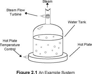
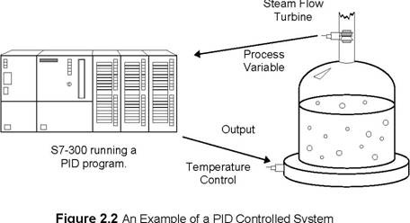
Figure 2.1 shows a picture of an example system to which a user might connect a PID controller. The figure shows a water tank sitting atop a hot plate, with a temperature control device for the hot plate and a small, monitored turbine for measuring the rate of the steam flow. This is a system that will work with a PID controller because of the relationship between the two variables: You can directly control the steam flow rate by adjusting the temperature of the hot plate. Figure 2.2 shows how both variables relate to the PID controller.
Copyright ![]() 1996 by SIEMENS page 2 / 15 Pid.doc Status: 11/96 Version 1.0
1996 by SIEMENS page 2 / 15 Pid.doc Status: 11/96 Version 1.0
SIMATIC S7-300/400 customers have free use of the application tips. These tips are only a general approach to using the S7-300/400 with various applications. Your specific application may be different. It is your responsibility to use the SIMATIC S7-300/400 properly in your applications.
The variable which represents the state of the system being controlled is called the ‘Process Variable.’ In our example above, you can see that the rate at which the steam spins the turbine is a good indicator of the event that we are trying to control: the speed at which the water is being boiled off. The output is the variable which, being altered by the controller, can affect the process variable by different degrees based on its intensity -- By turning the hot plate up, the water boils more quickly, more steam is produced, and the turbine’s speed increases.
Therefore, when a variable that accurately reflects the state of the process and an adjustable control which proportionally affects the process variable, then it is possible to use a PID controller. Common systems using PID controllers are air conditioning systems, solution mixing, heaters, etc.
Auto Mode vs. Manual Mode
There are two settings available on our PID controller. Putting a controller in Manual mode causes the PID loop do nothing, so that the user can directly control the output. The second, Auto, is the mode in which the PID loop is actually controlling the system. For the rest of this text, it will be assumed that the controller is in Auto mode.
What does the PID controller do, and how does it do it?
Quite simply, a PID controller adjusts the value of its output to try and balance the value of the process variable to a given ‘setpoint.’ To calculate the output value for a given instance, the controller finds the value of three different terms (using its user defined Sample time, Gain, Rate, and Reset values along with the calculated Error value): a Proportional term, an Integral term, and a Derivative term.
Output = MP + MI + MD
Formula 2.1
What are the Sample, Gain, Rate, and Reset, and where do they come from?
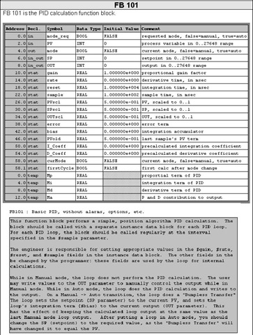
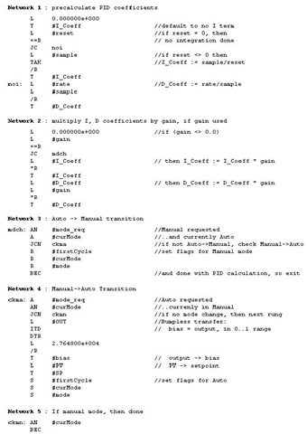
The sample rate is the cycle time (in milliseconds) at which the PID loop recalculates the output. The gain controls the sensitivity of the output calculation by affecting the influence of all the terms. The reset is a time given in milliseconds which is used to increase or decrease the influence of the Integral term in the equation. Finally, the rate value is used to control the influence of the Derivative term in the equation. Each of these values needs to be preset by the user before the PID controller starts.
If the user does not want integral action (no I in the PID calculation), then a value of infinity or a value of 0 should be specified for the integral time. If the user does not want derivative action (no D in the PID calculation), then a value of 0 should be specified for the derivative time. If the user does not want proportional action (no P in the PID), then a value of 0 should be specified for the gain (gain is normally a multiplier in the integral and derivative coefficient calculation, but is removed from the coefficient calculation, if gain = 0, to allow I, ID, or D loop control).
Copyright ![]() 1996 by SIEMENS page 3 / 15 Pid.doc Status: 11/96 Version 1.0
1996 by SIEMENS page 3 / 15 Pid.doc Status: 11/96 Version 1.0
SIMATIC S7-300/400 customers have free use of the application tips. These tips are only a general approach to using the S7-300/400 with various applications. Your specific application may be different. It is your responsibility to use the SIMATIC S7-300/400 properly in your applications.
How is the Error figured?
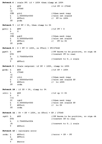
Error is figured as the difference between the normalized values of the setpoint and the process variable. The controller calculates this value in three steps. The first two steps are to change both the setpoint and the process variable into values that are based on a 0 to 1 (normalized) scale. This is done using the formulae:
SP = raw_SP / max_val
PV = raw_PV / max_val
Formulae 2.2 & 2.3
In the above formulae, the raw_SP and raw_PV values are the actual values that come into the controller, and the max_val term is the maximum value that either can take on. For example, if the values of raw_SP and raw_PV were being read in as values from 0 to 27,648, then the max_val term would have the value 27,648.
After these two values have been calculated, the error term is figured as follows:
Error = SP - PV
Formula 2.4
How is the Proportional term calculated?
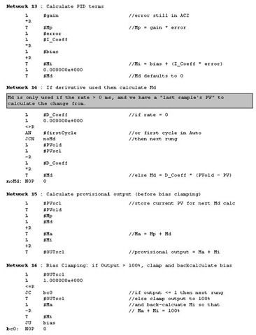
The proportional term, MP, is calculated using the following equation:
MP = Gain * Error
Formula 2.2
Going back to our earlier example with the water tank, the proportional term says that as the speed of the turbine increases further above the setpoint, the heat is decreased proportionally to bring the speed down. As the turbine slows below the setpoint, the heat is increased to proportionally to bring the speed up.
How is the Integral Term calculated?
The integral term, MI, is calculated using the following equation:
MI = Bias + (CI * Error)
Formula 2.3
In this equation, two new terms are introduced. The first, CI, is the coefficient of the Integral term, and is calculated from the Reset:
CI = Gain * (Sample / Reset)
Formula 2.4
Both the Sample and Reset terms were introduced earlier, but in this equation their uses become apparent. The larger the Reset value is, the less impact the integral term will have on the output, while larger Sample times give it a bigger influence (Sample time also affects the Derivative term, which will be explained later).
Copyright ![]() 1996 by SIEMENS page 4 / 15 Pid.doc Status: 11/96 Version 1.0
1996 by SIEMENS page 4 / 15 Pid.doc Status: 11/96 Version 1.0
SIMATIC S7-300/400 customers have free use of the application tips. These tips are only a general approach to using the S7-300/400 with various applications. Your specific application may be different. It is your responsibility to use the SIMATIC S7-300/400 properly in your applications.
The Bias term in Formula 2.3 represents (technically speaking) the area under the curve of a graph plotting the Error vs. time.
Abstractly, however, the Bias value (ideally) grows to an output level that keeps the system stable, letting the Proportional and Derivative terms handle any small fluctuations. In relation to our water tank example from earlier, this means that eventually the Bias portion of MI would be the only significant contribution to the final output value, and the MP and MD terms would only be active (non-zero) when a fluctuation occurred. At a time n the equations for MI and the Bias term are:
MI,n = Biasn-1 + (CI * Error)Biasn = MI,n
Formula 2.5
How is the Derivative term calculated?The derivative formula for a given time n is calculated with the following equation:
MD = CD * (PVn-1 -PVn)
Formula 2.6
This formula only introduces 1 new term, CD, which is calculated using Formula 2.7.
CD = Gain * (Rate / Sample)
Formula 2.7
The Sample term (which is also used in figuring CI) is the sample time from earlier. In the Derivative term, the Sample time is indirectly proportional to the derivative component, while the Rate is directly proportional.
What if the final output value is too high?
During many processes (such as the water tank example earlier), the Process variable doesn’t respond immediately to a change in the value of the output -- if the water in the tank were ice cold, then even an output of 100% is not going to cause an instantaneous increase in steam flow. Likewise, setting the output to 0% when the water is boiling doesn’t provide an immediate reduction in steam production.
Because of this ‘system inertia,’ the output value for a give time could take on a value greater than 100% or less than 0%. In response to this, the PID program implements Output Clamping. If the output is greater than 100%, then it is clamped to 100%. If the output falls lower than 0%, then it is held to 0%.
Copyright ![]() 1996 by SIEMENS page 5 / 15 Pid.doc Status: 11/96 Version 1.0
1996 by SIEMENS page 5 / 15 Pid.doc Status: 11/96 Version 1.0
SIMATIC S7-300/400 customers have free use of the application tips. These tips are only a general approach to using the S7-300/400 with various applications. Your specific application may be different. It is your responsibility to use the SIMATIC S7-300/400 properly in your applications.
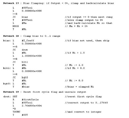
The only problem left to solve lies with the Bias portion of the Integral term. When the output for a system remains at 100% for a long period of time (such as when heating up cold water in our tank from earlier), the integral sum (which the Bias term represents) can grow to extremely large values. This means that when the variable starts responding, the Bias term will be keeping the calculated output well over 100% until it can be wound down. This generally results in the output swinging wildly from one limit to the other, but can be avoided using Bias Clamping.
There are a few different types of Bias Clamping, but the only pertinent one here is the one used in the program. There are two different conditions which cause Bias clamping to occur and two formulae as well:
If Output > 1
Bias = 1 - (MP + MD)
Formula 2.8
If Output < 0
Bias = -(MP + MD)
Formula 2.9
As the formulae show, when the Output grows to be greater than 1, the value of the Bias is adjusted so that the sum of MP, MD, and the Bias will be 1. Likewise, when the Output slips below 0, the value of the Bias is adjusted so that the above sum will be 0. The adjusted Bias value is then clamped such that its maximum value is 1 and its minimum value is 0.
What should be added to make the program work for the system?
1 Read in the Process Variable
2 Write the Output
3 Set the Setpoint
4 Adjust the scale for the Input and Setpoint
5 Adjust the scale for the Output
6 Adjust the Reset, Rate, Gain, and Sample time values.
Read in the Process Variable
The Process variable (the variable which accurately reflects the state of the system to be controlled) should be passed to the PV parameter of the function block.
Write the Output
The OUT parameter of the PID loop should be set to the analog output being controlled in the PID function block call.
Set the Setpoint
The user’s code must pass the Setpoint value to the PID function block via the SP parameter.
Copyright ![]() 1996 by SIEMENS page 6 / 15 Pid.doc Status: 11/96 Version 1.0
1996 by SIEMENS page 6 / 15 Pid.doc Status: 11/96 Version 1.0
SIMATIC S7-300/400 customers have free use of the application tips. These tips are only a general approach to using the S7-300/400 with various applications. Your specific application may be different. It is your responsibility to use the SIMATIC S7-300/400 properly in your applications.
Adjust the scale for the Process Variable and Setpoint
In networks 6 through 11 of the PID function block, the program converts the (raw) PV value into a normalized (0-1) value based on a scale of 0 to 27,648. If the value that the user is reading in is on a different scale, the user has to change the 27,648s in these networks to the new value. For example, if the scale were 0 to 100, you would change the 27,648s to 100s.
Another approach would be to change the scale of the PV and SP to the 0 to 27,648 scale before passing them to the PID function block. This could be done with code in the calling block, or by a scaling function block.
Adjust the scale for the Output
In the last network in the program, the Output value is changed from a normalized value (0-1) into a scaled number (0-27,648). As in the above section, to change the scale of the output, simply change the 27,648 into the new maximum value (or rescale the output after the function block returns).
Adjust the Reset, Rate, Gain, and Sample time values
The final thing that the user’s code needs to implement is the setting of the Reset, Rate, Gain, and Sample time values. If the PID loop’s instance DB is configured as retentive, this need only be done once, by hand, after the instance DB is created in the PLC. If the PID loop’s instance DB is not retentive, the loop tuning parameters must be set after each PLC restart. This could be done in OB100 (Complete Restart OB). For a PID loop instance data block n, the values
should be placed as follows:
Reset
� DBn.DBD18 (real), time in milliseconds
Rate
� DBn.DBD14 (real), time in milliseconds
Gain
� DBn.DBD10 (real), unitless factor
Sample
� DBn.DBD22 (real), time in milliseconds
The sample time should be set to the same period at which the PID loop function block called.
Adjusting the Reset, Rate, Gain, and Sample time, and Mode during run-time Changes in the Reset, Rate, Gain, and Sample time values take effect the next time the PID loop function block is called.
The PID loop mode is controlled via the mode_req function block parameter. When mode_req is FALSE (0), the loop will transition to or remain in Manual mode when the function block is next called. When mode_req is TRUE (1), the loop will transition to or remain in Auto module when the function block is next called.
Copyright ![]() 1996 by SIEMENS page 7 / 15 Pid.doc Status: 11/96 Version 1.0
1996 by SIEMENS page 7 / 15 Pid.doc Status: 11/96 Version 1.0
SIMATIC S7-300/400 customers have free use of the application tips. These tips are only a general approach to using the S7-300/400 with various applications. Your specific application may be different. It is your responsibility to use the SIMATIC S7-300/400 properly in your applications.
![]()
This is not part of the PID program per se, but shows how the PID function block is called.
![]()
The symbol table attaches functional names to PLC memory addresses. The functional names will be used in the example program.
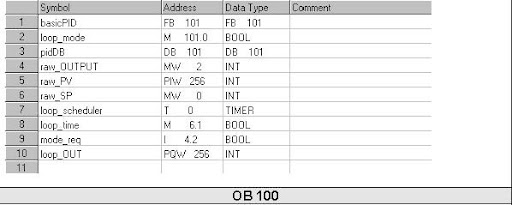
OB 100 is executed once when the PLC program starts after being in program mode, or turned off. If the PID instance data block is not retentive, OB100 is an appropriate place to load the data block with gain, rate, reset, and sample time values.

Copyright ![]() 1996 by SIEMENS page 8 / 15 Pid.doc Status: 11/96 Version 1.0
1996 by SIEMENS page 8 / 15 Pid.doc Status: 11/96 Version 1.0
SIMATIC S7-300/400 customers have free use of the application tips. These tips are only a general approach to using the S7-300/400 with various applications. Your specific application may be different. It is your responsibility to use the SIMATIC S7-300/400 properly in your applications.
S7-300/400 Tip PID Tip No. 2
OB 1
OB 1 is the main “scanned” portion of the PLC program. It is executed as often as possible while the PLC is in Run mode. The example program periodically calls the PID function block from OB 1.
Copyright ![]() 1996 by SIEMENS page 9 / 15 Pid.doc Status: 11/96 Version 1.0
1996 by SIEMENS page 9 / 15 Pid.doc Status: 11/96 Version 1.0
SIMATIC S7-300/400 customers have free use of the application tips. These tips are only a general approach to using the S7-300/400 with various applications. Your specific application may be different. It is your responsibility to use the SIMATIC S7-300/400 properly in your applications.
S7-300/400 Tip PID Tip No. 2
Copyright  1996 by SIEMENS page 10 / 15 Pid.doc Status: 11/96 Version 1.0
 SIMATIC S7-300/400 customers have free use of the application tips. These tips are only a general approach to using the S7-300/400 with various applications. Your specific application may be different. It is your responsibility to use the SIMATIC S7-300/400 properly in your applications.
S7-300/400 Tip PID Tip No. 2
Copyright ![]() 1996 by SIEMENS page 11 / 15 Pid.doc Status: 11/96 Version 1.0
1996 by SIEMENS page 11 / 15 Pid.doc Status: 11/96 Version 1.0
SIMATIC S7-300/400 customers have free use of the application tips. These tips are only a general approach to using the S7-300/400 with various applications. Your specific application may be different. It is your responsibility to use the SIMATIC S7-300/400 properly in your applications.
S7-300/400 Tip PID Tip No. 2
Copyright ![]() 1996 by SIEMENS page 12 / 15 Pid.doc Status: 11/96 Version 1.0
1996 by SIEMENS page 12 / 15 Pid.doc Status: 11/96 Version 1.0
SIMATIC S7-300/400 customers have free use of the application tips. These tips are only a general approach to using the S7-300/400 with various applications. Your specific application may be different. It is your responsibility to use the SIMATIC S7-300/400 properly in your applications.
S7-300/400 Tip PID Tip No. 2
Copyright ![]() 1996 by SIEMENS page 13 / 15 Pid.doc Status: 11/96 Version 1.0
1996 by SIEMENS page 13 / 15 Pid.doc Status: 11/96 Version 1.0
SIMATIC S7-300/400 customers have free use of the application tips. These tips are only a general approach to using the S7-300/400 with various applications. Your specific application may be different. It is your responsibility to use the SIMATIC S7-300/400 properly in your applications.
![]()
The SIMATIC S7-300/400 Application Tips are provided to give users of the S7-300/400 some indication as to how, from the view of programming technique, certain tasks can be solved with this controller. These instructions do not purport to cover all details or variations in equipment, nor do they provide for every possible contingency. Use of the S7-300/400 Application Tips is free.
Siemens reserves the right to make changes in specifications shown herein or make improvements at any time without notice or obligation. It does not relieve the user of responsibility to use sound practices in application, installation, operation, and maintenance of the equipment purchased. Should a conflict arise between the general information contained in this publication, the contents of drawings or supplementary material, or both, the latter shall take precedence.
Copyright ![]() 1996 by SIEMENS page 14 / 15 Pid.doc Status: 11/96 Version 1.0
1996 by SIEMENS page 14 / 15 Pid.doc Status: 11/96 Version 1.0
SIMATIC S7-300/400 customers have free use of the application tips. These tips are only a general approach to using the S7-300/400 with various applications. Your specific application may be different. It is your responsibility to use the SIMATIC S7-300/400 properly in your applications.
S7-300/400 Tip PID Tip No. 2
Siemens is not liable, for whatever legal reason, for damages or personal injury resulting from the use of the application tips.
All rights reserved. Any form of duplication or distribution, including excerpts, is only permitted with express authorization by SIEMENS.
Copyright ![]() 1996 by SIEMENS page 15 / 15 Pid.doc Status: 11/96 Version 1.0
1996 by SIEMENS page 15 / 15 Pid.doc Status: 11/96 Version 1.0
SIMATIC S7-300/400 customers have free use of the application tips. These tips are only a general approach to using the S7-300/400 with various applications. Your specific application may be different. It is your responsibility to use the SIMATIC S7-300/400 properly in your applications.
![clip_image002[7]](http://lh5.ggpht.com/nawaphun/SCmPQbtiLfI/AAAAAAAAAJU/W6n19LT2r-g/clip_image00272.jpg)
![clip_image004[7]](http://lh4.ggpht.com/nawaphun/SCmPTLtiLhI/AAAAAAAAAJk/Afi2VmFgdqg/clip_image00472.jpg)
![clip_image010[7]](http://lh5.ggpht.com/nawaphun/SCmPcbtiLnI/AAAAAAAAAKU/A_G6B-TryM0/clip_image01072.jpg)
![clip_image014[7]](http://lh5.ggpht.com/nawaphun/SCmPibtiLrI/AAAAAAAAAK0/idhtzfheBDg/clip_image01472.jpg)
![clip_image017[7]](http://lh6.ggpht.com/nawaphun/SCmPortiLvI/AAAAAAAAALU/Y14rUt2RLME/clip_image01772.jpg)
![clip_image020[7]](http://lh5.ggpht.com/nawaphun/SCmPvbtiLzI/AAAAAAAAAL0/wbHkpsNVx0s/clip_image02072.jpg)
![clip_image021[7]](http://lh4.ggpht.com/nawaphun/SCmP3LtiL3I/AAAAAAAAAMU/3vn7hEXq510/clip_image02172.jpg)